
TUTORIALS: TIRE AND WHEEL RIM, Part 3
LIGHTING AND CAMERA, TEXTURING AND RENDERING
I will apply a highly reflected chrome texture to the wheel rim and will use bump mapping on the rubber tire to describe certain detail. In order to fully evaluate those effects, I must first set up an environment and lighting rig. Lighting determines how shadows are casts, including those generated by bump maps, and how colors are perceived. Maya offers a default lighting rig -- without it we would not be able to see our mesh at all within the viewports or in the renders. However, since I plan to eventually illuminate my scene with a specific light scheme, I want to create that rig first, so I can accuratelyI test my textures.
RENDER SETTINGS
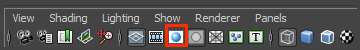
Since I will be using Mental Ray to render my final images, it makes sense at this point to test my lighting and textures with it as well. If Mental Ray does not show up as an option for rendering, select Window/Settings Preferences/Plug-in Manager and scroll down to Mayatomr.mll and check the load option boxes.
I want the quality of my test renders to be the same as the final render. I set the Quality Presets, under the Quality tab in the Render Settings window, to "Production" and I set my Shadow Maps Format, under the Shadows section, to "Detail" for smooth shadow contouring. To speed up rendering for the test renders, I opt for a small size in the Image Size section, under the Common tab in the Render Settings Window.
As mentioned previously, the Mental Ray renderer not only provides users with some beautiful texture options, but it also allows me to render the smooth preview without formally subdividing the mesh. This feature is extremely handy for iterative modeling passes -- but can only be used with the Mental Ray for Maya renderer. In order to obtain smooth render effects, you must enable the Export Triangulated Polygons option in the Render Settings/Mental Ray /Options tab under the Translation/Performance sub-section.
LIGHTING AND CAMERA
In order to test my cast shadows, I want to establish a simple environmental mesh: in this case a backdrop or plane that gently slopes up.
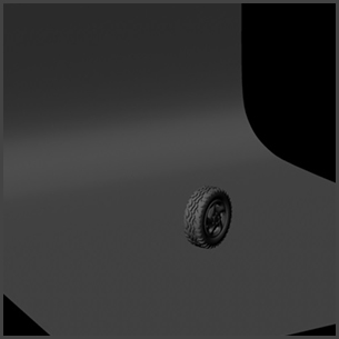
The backdrop's eventual textures will be used to establish a reflection for the chrome wheel rim, but for now, I can test the lighting with just the default Lambert shader.
Next, I will define a fixed view for rendering and assign it to a newly created perpsective camera, which I rename "render camera". Within the Render Settings Window, I assign an aspect ratio to my render camera, which, in this case, is derived from the 640x480 preset.
Using the resolution gate in the viewport panel previews how the image will be cropped within a given aspect ratio inside the viewport.
Once the placement and camera angle are finalized, I lock the camera's transform settings within the Channel Box Editor. That way, I can't indadvertantly move the render camera as I work on other scene components.
Once the render camera is set, I use its position and orientation to setup a three point lighting scheme.
A three point lighting scheme consists of a Key Light, a Fill Light, and a Rim Light (also called Back Light). Create the Key Light first. The Key Light is the dominate source of illumination and casts the darkest shadows. Specular highlights are triggered by the Key Light. For this tutorial, I am using a Directional Light (Create/Lights/Directional Light) for my Key Light.
I will start with a basic placement, which, I can refine as I add more lights and create textures for my final render. From the top view, I offset the Key Light about 40 degrees to the right of the render camera. From a side view, I raise the Key Light above the camera and rotate it about 35 degrees into place so that it shines directly on the tire.
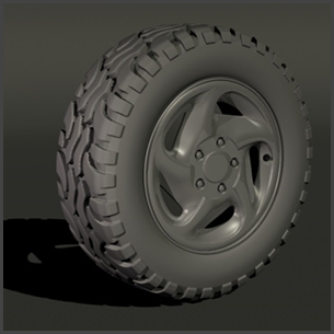
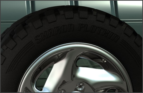
My test render with just the key light should have a nice balance and contrast between light and dark, and shading that uses all of the grays in between. It should look almost like the final rendering, except that the shadows are pitch black and it has very harsh contrast. I am using a default grey Lambert shader for all the objects, except for the rim, which is using a slightly shiny Phong shader.
Next, I add a spotlight as a Fill Light. The Fill Light softens and extends the illumination provided by the key light, and makes more of the subject visible. The Fill Light will simulate the reflected and bounced light in the scene. From the top view, a Fill Light is generally placed in a 90 degree angle to the Key in relation to subject and on the opposite side of the camera. In this scene, the Key is on the right side of the camera, so the Fill is placed on the left. From the side view, I raise it above the tire and angle it to point towards the subject. Only the Key Light generates shadows.
The Rim Light (also called Back Light) helps define the back edge of the tire object, to help visually separate it from the background. From the top view, I add a spot light, and position it behind the tire, opposite from the key. In a side view I raise it above the tire and rotate it so that it is pointed toward the subject.

The three point lighting scheme is a great starting point for my scene's lighting rig. Once I have added textures, I will make further refinements to the lights. In the Attributes Window, under the shape tab for each light, I will adjust the color and intensity for all three lights, and the cone angle, penumbra and dropoff for the spotlights. The cone angle defines the radius of illumination. The penumbra and dropoff soften the edge of the spotlight from either beyond or within the radius of illumination. I can further specify which objects in a scene are excluded from illumination by specific lights by selecting the Light Linking Editor (Rendering Menu Set/Lighting/Shading) and choosing either the Light-Centric or Object-Centric option.
TEXTURES
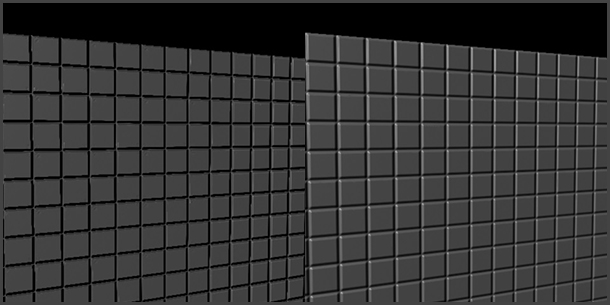
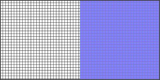
I will be applying mostly Tangent Space Normal Maps to the Bump channel of my shaders in order to add surface detail to my objects. I prefer normal maps to grey-scale height maps. As you can see in the following examples, use of the normal maps add a level of contouring not present when using grey-scale height maps. The normal map effect is on the right:

The Rubber Tire Texture
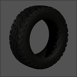
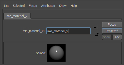
I will apply a rubber material to the tire, using Mental Ray's mia_material_x, a versatile and physically correct shader. The mia_material_x, is found under Mental Ray tab in the Hypershade window and offers a number of presets including one for rubber. I can access those presets when I open the Attributes window for the shader.
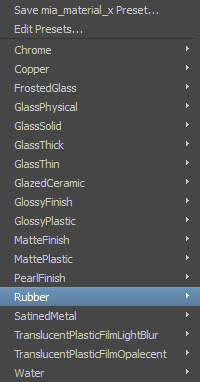
The rubber texture by itself is very convincing, but I would like to add just a bit of roughness to its surface via the Bump channel using a procedural fractal texture. I also want to emboss words on the sidewall of the tire with a second bump map derived from a bitmap image.
With a standard Maya texture, like a Blinn or a Lambert, I can simply combine the two maps using a Layer Texture in the Bump channel. Unfortunately, the Bump channel in mia_material_x does not recognize the Layer Texture filtering and only uses the file information from the top layer.
Another approach is to create a Layer Texture out of the two mia_material_x textures, one with the roughened texture and one with the embosses words. However, the Layer Texture node does not directly support the mia_material_x. There is, though, a very simple work around and that is to use Surface Shaders to encapsulate the mia_materials. A Surface Shader basically acts as an empty shell because it does not respect lighting information. It will accept the mia_material_x, along with its lighting information, and in turn, is accepted by the Layer Texture.
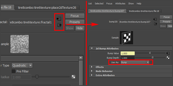
To get started, I will create two tire materials, one with a grainy surface texture and one with embossed type. Under the Hypershade window Create tab, I select mia_material_x from the Materials submenu within Mental Ray. Double clicking on the new material brings up the Attribute Editor. For clarity, I name this material, "tire_texture". Under the Presets* button, I select "Rubber". I scroll down to the Bump section of the material's attributes, and select the link button for the "Standard Bump". From there, I am given the option to link with a texture, and I choose the Fractal procedural texture. Using the navigational arrows, to select input and output connections, I select the output arrow to open the 2d Bump Attributes tab. By default the "Use As" option is set to "Bump", which is appropriate for the grey scale fractal which I will use as a basic height map.
I adjust the amplitude, ratio, max level and frequency until my test render gives me just the hint of a fine grainy texture on the tire's surface.
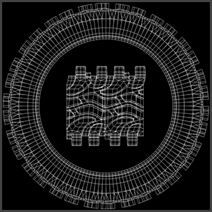
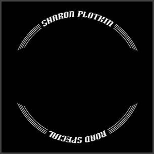
For the second tire material, which I will name "tire_logo", I am going to link my Standard Bump to an external file, a normal bump map I created in Photoshop, with words arranged in a circular shape. I need to create template first, which I can do by exporting the UV information from Maya. With the tire selected, I open the UV Texture Editor in Maya, and under the Polygons pull menu, I select UV Snapshot. I like working in the texture size of 1024 pixels squared. (Maya defaults to texture sizes which are powers of 2.) The UV Snapshot creates an image of the polygonal edges of the mesh within a specified quadrant of the texture space, which by default is the normalized space, or "0 to 1" range.
Within Photoshop, I open the UV image and convert the background level into a layer, which in turn, I apply as an overlay to guide the text placement.
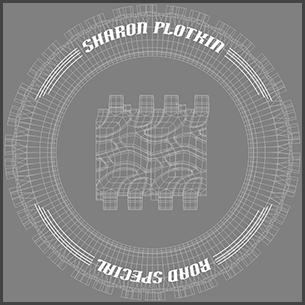
Thinking in terms of a height map, with white as the most pronounced and black as the most recessive values, I choose a 50% neutral grey for my background color. Once my type is in place, I convert the greyscale image into a normal map using a plugin utility for Photoshop, from Quixel, called nDo. (http://dev.quixel.se/ndo)
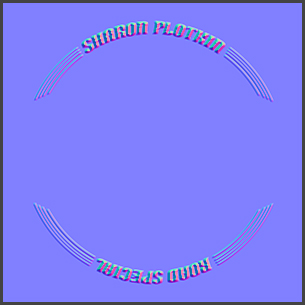
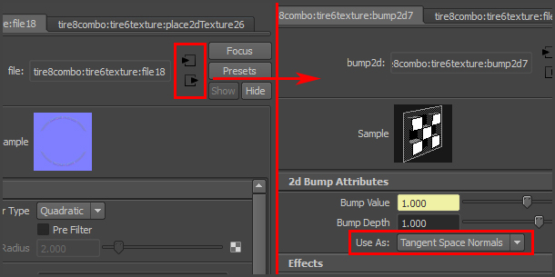
As, with the fractal height map, I scroll down to the Bump section of the material's attributes, and select the link button for the "Standard Bump". From there, I am given the option to link with a texture. Since I am using a normal map for my second tire material, "tire_logo", I specify that it is used as a Tangent Space Normals.
I apply this second material to the tire, replacing the first tire texture, and once I am satisfied with my test render, I can combine the two materials. I create two Surface Shaders, one for each material, which I link through the Out Color channel under the Surface Shader Attributes in the Shader's Attributes window. (Surface Shaders are available under the Create tab in the Hypershade Window, in the Surface section under Maya shaders.)
Once each mia_material is encapsulated inside a Surface Shader, I create a Layered Texture. Layered Textures can be found in the Other Textures section under the Hypershade Create tab. Within the Layered Texture Attributes, in the Attributes window, I create two layers by dragging and dropping the two newly created Surface Shaders from the Hypershade window into the layer workspace.
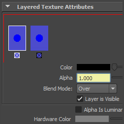
The left most layer is the top layer, which is the logo material. I will be using the " Over" option for my Blend Mode, so I will need to link the Alpha channel to a mask, where black represents transparency.
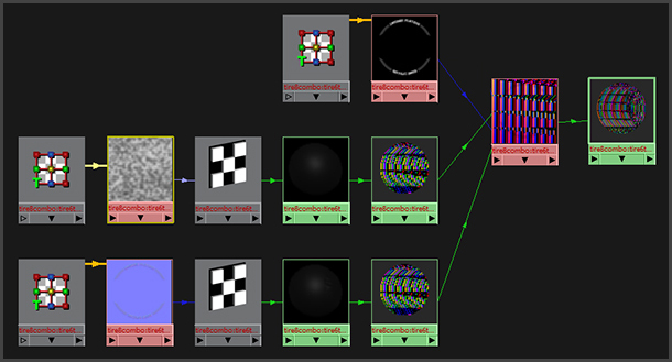
Once my Layer Texture is complete, I will need to encapsulate it inside a Surface Shader so that it may be applied to the tire mesh.
Here is the shader graph:
The Backdrop Texture
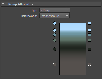
Before I set the material for the reflective chrome rim, I need to define the texture for the backdrop. The texture for the backdrop, which is the simple plane that gently rolls up, will set the mood for my composition. I am using a mia_material_x, with a Glazed Ceramic Preset. I am using a VRamp in the color channel to describe the muted colors that will nicely offset the dark rubber in the tire.
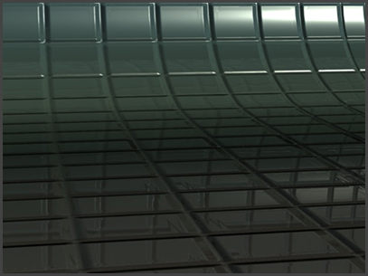
I am using a simple grid pattern for the normal map that I will place in the Bump Channel.
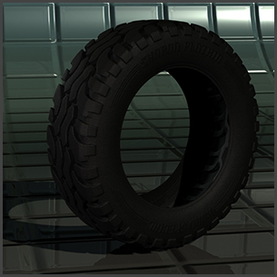
In my test render, I can see that the tire is offset nicely from the background.
The Wheel Rim Texture
Now that I have the environment mapped, I can create the highly reflective chrome wheel rim texture. I assign a Blinn shader to the wheel rim mesh. Under Specular Shading Section, I link the Reflected Color to an Environment Sphere, whose Image channel, in turn, is linked to the same Vertical Ramp that is used for the backdrop color channel.
To enhance the reflected qualities of the Blinn shader, I set the Color, Transparency, Ambient color and Incandescence to black and Diffuse to black or "0". Under Specular Shading, I set the Eccentricity to 0.250, the Specular Roll Off to 1.000, the Specular Color to white and the Reflectivity to 0.800.
Under the Hypergraph Create tab, within the default Maya shaders, I select Env Textures and choose the Env Sphere. With the Environment Sphere selected, I transform its attributes in the Attributes Window. I translate it up along the Y axis by 93 units and non-uniformly scale it in XYZ at 150, 100, 300 percent respectively. To link its Image channel to an existing texture, I simply select the Hypergraph Textures tab and drag the existing texture onto the sphere's Image channel color box in the Attributes editor.
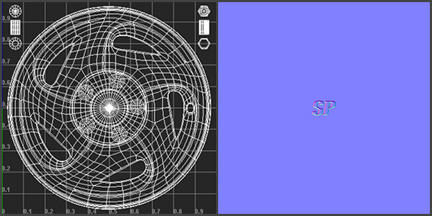
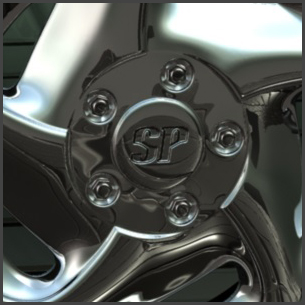
Finally, I want to add a bump map to suggest an engraved logo on the cap. As, I demonstrated with the tire logo texture, I use the UV information from the wheel rim to create a template which I can open in Photoshop and use as an overlay layer to guide my type placement.
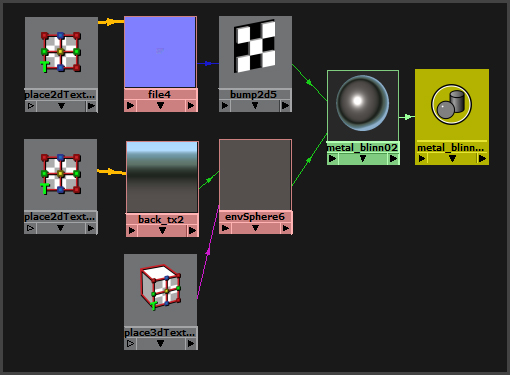
I link the normal map to the Bump Mapping Channel under the Common Material Attributes for the Blinn shader for the finishing touch. Here is the shader graph:
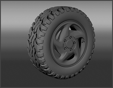
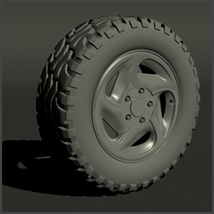
The Final Render
With all the scene components now completed, I make a final pass on the lighting, texture inputs and camera angle. Saving in iterations allows me to compare effects and saves me the pain of accidentally writing over a good file with a bad experiment. As always, I back up my final work on to an external drive at the end of each day.
I hope you enjoyed this tutorial. I look forward to reading your comments and questions.
![]()
![]()
![]()