
TUTORIALS: TIRE AND WHEEL RIM, Part 1
A great segue into 3D vehicle design is to begin with a basic tire and wheel rim assignment. The following tutorial takes the reader through the entire production arc: starting with tips on basic design and pre-production preparation in Photoshop, followed by modeling, lighting, texturing and rendering lessons in Autodesk's Maya.
This is an intermediate-level tutorial. I assume the reader has a basic working knowledge of the Maya interface and tool set. For a more basic and broad-based introdution to Maya' s toolset I recomend the reader visit https://courses.cs.washington.edu/courses/cse458/05au/reading/
DESDIGN AND PREP
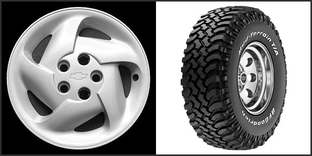
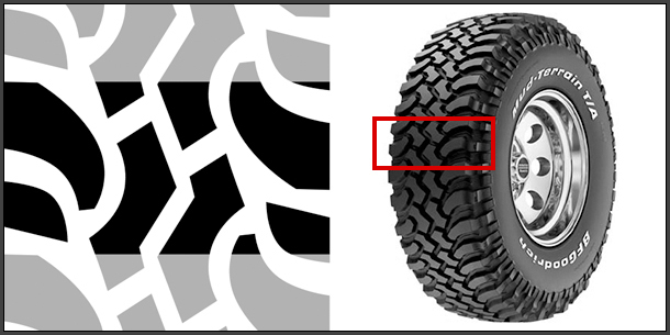
Before I commit to any kind of modeling assignment, I make sure my design is interesting and solid from all viewing angles. I start by researching my subject and putting together a collection of images that I can use as visual reference. For this tutorial, my 2D reference will consist of a tread design and an orthographic side view of a tire and rim. A three quarters view will also be used as reference to help maintain proportions throughout the modeling process.
I arrived at a hybrid design, based on the treads from one tire image and the hubcap shape from another. The tire treads offer a very clear pattern and the hubcap shape with its interlocking curved topology will present a nice modeling challenge.
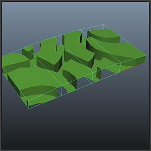
Based on the three quarters view I defined a width to height ratio for my tire, which I blocked out with a primitive cylinder shape.
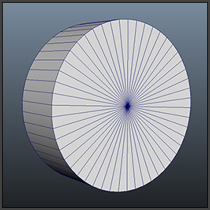
The cylinder is 30 units deep with a radius of 45 units. When creating a series of models for the same project, it is important to establish a universal system of measurement. By default, Maya uses cm's as its unit of measurement. I can adjust my measurement system to reflect these units as real world coordinates, or I can devise a scale, where for example, 100 units = 6 feet. Whatever I choose, it is important that I remain consistent.
Creating the Tire Treads Template
There are different ways to create tire treads. I am going to use a method where the treads are created as extrusions from the surface of an elongated plane, which in turn, is bent 360 degrees to form a round shell.
Using the cylinder shape as a template, I know that the approximate width of my plane is 30 units. To determine its length, I want to calculate the circumference of the cylinder. I take the radius, which is 45 units and multiply it by 2π. In this case, I will use 3.14 to equal "π". This gives me a length of 282.6 units, which I can round off to 283. Since I am modeling for appearance, as opposed to manufacturing, I allow myself a little wiggle room.
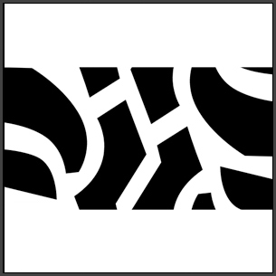
Next I define the basic pattern unit that I will model once as a segment and then duplicate until I have created the entire length of the tread. For this project, I have adapted and simplified a tread design I found in photo reference. I am starting out with shapes that describe only the top of the tread. (The sides will be extruded in later steps.) The aspect ratio of the basic pattern unit is a convenient 2:1.
Observe how the basic pattern unit tiles vertically. I can test this affect by using the offset function in Photoshop (Filter/Other/Offset). Furthermore, using repeating shapes can speed up the modeling process. Complexity is added to this pattern by horizontally mirroring a basic element, and then flipping and offsetting it vertically on the opposite side.

Once I have defined the basic pattern unit, I place it in a square image. This step is optional, but keeping textures that will be used for guides in a 1:1 aspect ratio makes it easier to create reference planes.
Maya accepts a variety of image file formats. I prefer JPEG's for flat images and TIFF's for layered images with alpha channels.
MODELING
Modeling the Tire Treads
In Maya, starting in the Polygon Menu Set, I create a square reference plane and center it along X and Z axes and slightly lower by a unit or 2 along the Y axis. My plane width and height parameters are set to 30. I link the tread template image to a Lambert shader, which I in turn, apply to the plane, and then with the plane selected, add the plane to a layer (Channel Box/Layer Editor - Layers/Create Layer from Selected). I mark the layer as "R" for "Referenced" so that the objects within can be seen but not inadvertently selected or transformed.
Occasionally, textures may appear blurry in the viewport. I correct this by selecting either "High Quality Rendering" or "Viewport 2.0" under the viewport's Renderer tab.
In a new non-referenced layer (Channel Box/Layer Editor - Layers/Create Empty Layer), I create a plane, centered along all three axes, that will form the base of my tire tread mesh. I start with just one subdivision for the height and the width. From the top viewport, in vertex mode, I align the edges symmetrically with the outer edges of the tread template pattern unit.
I assign a new shader to this plane and for ease of selection, select a color other than grey. Adjusting the transparency levels on the base tread shader will allow me to view the source image from below.
Under Edit Mesh, I select the Insert Edge Loop tool and begin adding internal edges. I translate vertices to follow the contour of the shapes and model in quads as much as possible. The resolution can be somewhat crude, because the edges will eventually be refined using a smoothing function within Maya.
Once the contour lines have been added and adjusted, I check the alignment of the top edges of vertices to the bottom. I create a couple of instanced objects that are offset to align with the top and bottom edges of the tire tread plane. Once vertices positions are adjusted the instanced copies can be discarded.
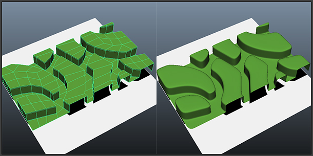
Up to this point I have been modeling on a flat plane. I can now add volume through extrusions. I select all the faces that align with the pattern and under Edit Mesh, I select the Extrude function to raise the planes. I insert extra edge loops near the top and base of the extrusion, so that the mesh retains the desired definition when viewed in Smooth Mesh Preview mode.
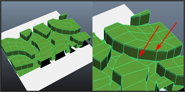
The Smooth Mesh Preview mode quickly shows me how the polygon mesh will appear when smoothed, without actually applying a smoothing operation. Toggling between the "3" key and the "1" key allows me to alternate between the smooth mesh and default viewing modes.
Working in the smooth mesh preview mode is efficient for tweaking a mesh prior to an actual smooth mesh operation. It does not record any smoothing history and it allows users to make changes to the components on the smooth mesh preview itself without the cage necessarily being visible. (The cage overlay, which is derived from the lower poly mesh, can be previewed over the smoothed mesh by selecting the "2" key.)
I will be using this modeling strategy throughout the tutorial.
Next, I will add a slight arc to profile of the treads, as would be seen in a cross section of a tire. In the Animation Menu Set, with the tread object selected, I select Create Deformers/Lattice Options. My Free Form Deformation lattice has 5 S Divisions, 2 T Divisions and 2 U Divisions. I right click on the lattice, and select Lattice Points which I translate to modify the shape.
Returning to the PoIygon menu set, I continue modeling out the tire walls. I extrude selected faces horizontally to continue the tread pattern on the sides.
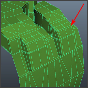
I complete the tire's side wall profile, by extruding side edges downward and inserting edge loops as needed. The goal is to use an economy of vertices. Toggling between the smooth mesh preview and default view modes helps to ensure that the mesh will smooth correctly, while maintaining volume. Modeling in quadrangles allows for the easy insertion of edge loops and helps keep the mesh's topology regular when smoothed.
Setting the Tire UV's
In my next modeling step, I will duplicate and offset copies of the tread section to create the entire length of the tire object. Before I do that, however, I will assign UV's to the top of the treads. UV's determine how a texture is mapped onto the surface of a mesh. Usually, UV's are assigned when the mesh's modeling is complete, because UV's are based on the vertex information. In this case, I want the texture to repeat with the tread section. Assigning UV's to the top of the treads, before they are duplicated, is therefore more efficient, with fewer components to edit, plus a simple planar projection can be used to create the UV's.
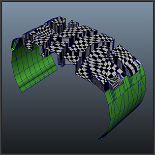
I select the mesh object, and right click to select face mode. I select only the faces that form the top extrusions. In the Hypershade window I create a new Lambert shader and assign it to the newly selected faces.
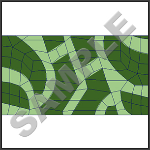
Under the shader's common material attributes, I link the color channel to a procedural checker pattern. I will use this pattern as a way to ensure that when the UV's are assigned they do not distort the texture. I navigate to the 2d Texture Placement Attributes to adjust the tiling on the checker pattern. (In Part 3 of this tutorial, I explain how to navigate within the texture's Attributes Window using the Input/Output Connection arrows.)
Under the viewport options, I select the display texture option -- or hot key "6". A distorted checker pattern appears on the selected faces. Since the mesh was created from a parametric plane, with inherent UV's, the checker pattern is visible, but distorted due to the subsequent mesh edits.
Vestiges of the old planar coordinates can also be seen in the UV Editor window (Window/UV Texture Editor). To see this effect more clearly, within the Texture Editor, under the Image tab, I select Display Image and Display Unfiltered.
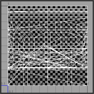
To correct the distortion, I assign a planar map. With the only the face components I want mapped still selected, I choose, under the Create UV's pull down menu, Planar Mapping Options and select the Y axis projection option before completing the function.
The checkers are placed more regularly, but may still appear elongated.
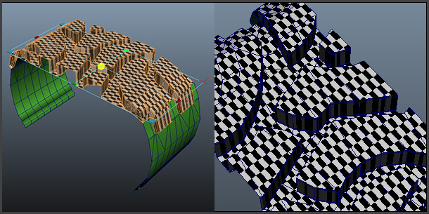
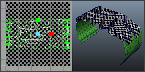
Using the UV Texture Editor I square up the checker pattern, so that texture's pixels are not distorted. With the mapped faces still selected, I right click and convert the selection to UV components. The UV's for the top treads may be difficult to discern, because they are displayed on top of the faces for the side walls. To separate, I move the selected UV's to side, then marquee select the UV's for the other faces and move them to another side for later editing.
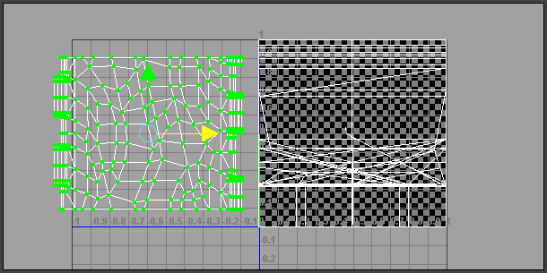
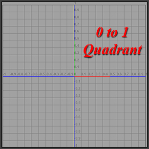
I return the top tread UV's to the 0 to 1 quadrant of the UV grid and apply a non-uniform scale until the checker pattern appears squared in the viewport. This is as far as I need to take the UV edits for now. I will discuss the topic further, once the mesh for the tire is completed.
Now that the UV's have been set for the basic tread segment, it is ready to be duplicated and offset. Under the Edit menu I select Duplicate Special Options/Copy and Group under Parent. For this model, I set translation in X to 15.75 units (the length of my base unit) and specified 17 copies for a total length of 283 units
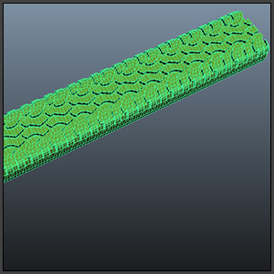
I merge coincidental vertices. Under Edit Mesh, I select Merge options to set a threshold -- I use a fairly low setting of .0010. This allows the user to marquee select multiple vertices, but merge only the ones which are placed coincidentally to one another. This may take some experimentation.
I can monitor my results by using the Poly Count heads up display, which is accessible under Display/Heads Up Display/PolyCount. The goal is to reduce the number of vertices to their absolute minimum without reducing the number of faces or triangles. Toggling the smooth mesh preview may also help check for gaps that may result from unmerged vertices.
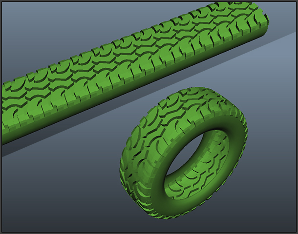
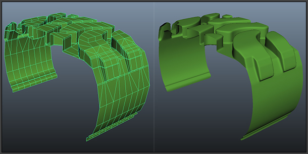
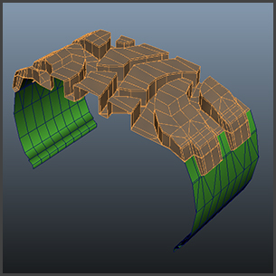
Once all the coincidental vertices are merged, I may bend the mesh to form the tire shape. In the Animation menu set, with the tread object selected, I apply, under the Create Deformers menu, the Nonlinear/Bend function. With the tread object still selected, I open the Channel Box Editor and under INPUTS, select "bend1" to adjust the degree of Curvature. The degree of curvature is a function of π. This may take a little experimentation to arrive at the just the right value to insure that the ends will nicely align. For my model, I choose a curvature of -3.1416.
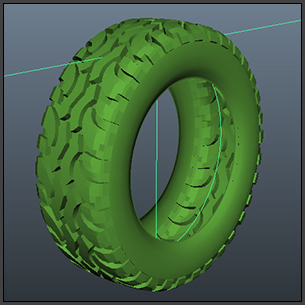
Returning to the Polygon menu set, I complete the process by merging the coincidental vertices and check for gaps by viewing the mesh in the Sooth Mesh Preview mode. Once satisfied, I delete the history (Edit/Delete by Type/History).
Part 4: Create the Final UV's for the Tire
With the modeling portion completed for the tire, the next step is to prep the surface for texturing by editing the UV's. UV's define a two-dimensional texture coordinate system and are based on the vertex information for polygonal and subdivision surface meshes. As mentioned previously, UV's determine how an image texture is mapped onto the surface mesh, by controlling which pixels on the texture map correspond to particular vertices on the mesh.
Typically, I want to normalize the UVs for all selected faces collectively. That means the texture coordinates for all selected faces are “collectively” fit into the 0 to 1 texture space. This is the default. Textures will appear to tile on meshes whose faces extend beyond the 0 to 1 texture space.
Since the UV's have already been set for the top of the treads, I will focus on setting them for the side wall. Having already isolated the side wall polygons when the tops tread UV's were created will save me a lot time. Instead of laboriously selecting the faces in the viewport, I can simply select them in the UV Editor Window.
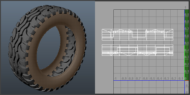
The arrangement of UV's depends on the tire design and the kind of information I want to convey with the texture. In this design I want to apply curved text to the side walls. Working in face mode and with only the side wall polygons selected, I create a planar projection map. I choose Create UV's/Planar Mapping Options and select the X axis projection option before completing the function. Using a checker pattern as a guide, I scale the UV's for the top tread faces so that they are approximately at the same resolution as the faces on the sidewalls.
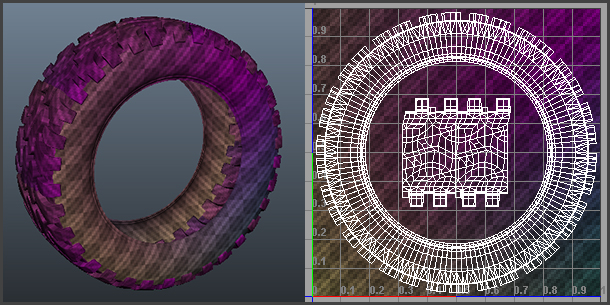
With the geometry complete for the tire, I will model the wheel rim in the next section.
![]()
![]()
![]()