
TUTORIALS: RIGGING FOR INVERSE KINEMATCS
This tutorial offers an introduction to basic rigging, using a pair of legs as my model. I describe the process for creating an animation skeletion, applying Inverse Kinematics and establishing controllers and constraints.
This is an intermediate-level tutorial. I assume the reader has a basic working knowledge of the Maya interface and tool set. For a more basic and broad-based introdution to Maya' s toolset I recomend the reader visit https://courses.cs.washington.edu/courses/cse458/05au/reading/
INVERSE KINEMATICS vs. FORWARD KINEMATICS
In 3D computer animation, FK, or Forward Kinematics, refers to the forward effect through the hierarchical chain, of transforms (movement, rotation, scale) from the parent onto the child nodes. Transformations to the parent are translated down to the child node and are based around the parent's pivot point, The parent's orientation, conversely, is not affected by the child's orientation. Moving a child object will simply offset it from the parent, in this instance.
IK, or Inverse Kinematics, refers to a process where as the child node moves, it inversely effects its parents' position and orientation values. IK is handy in animation for structures like limbs in cases where you might want to animate, say, a walk cycle. Without an IK handle your limbs can stretch and move at strange angles. With an IK handle your limbs will remain at the correct length and, if set properly, will automatically bend in the correct direction.
Both FK and IK are used in 3D animation. There is no one "right" way to animate a scene and sometimes the choice to use FK over IK is left to the discretion and preference of the animator.
This introductory level tutorial demonstrates how to create a basic IK rig for a pair of legs. This rig will use control objects to position and orient feet and knees. A rudimentary understanding of the Maya user interface and viewport navigation is required.
CREATE THE SKELETON
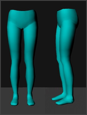
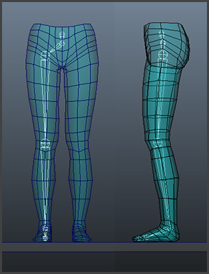
For this tutorial, I have modeled a pair of legs which are symmetrically mirrored along the X axis, with positive X facing right, in a world coordinate system where Y is up -- the default setting in Maya. I am also using centimeters, the default unit of measurement.
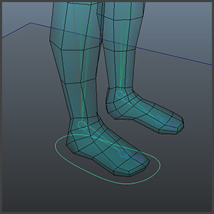
You'll see that there is a slight bend to the knees in the mesh itself, which the leg joints should mimic. This is important because, the position of the joints affected by an IK handle should indicate the direction they will be bending. In this case, the knee joints should be positioned just forward of the hip and ankle joints.
You will mostly be working within the Animation menu set for this tutorial. Under the Skeleton menu, select the Joint Tool. When creating a skeleton, you are actually creating joints that are hierarchically connected. It's important to create joints in an orthographic viewport. In the front orthographic view, left-mouse-button click just above the leg mesh, roughly centering your curser along the X-axis. Select "Enter" to complete the joint creation and in the Channel Box editor, type "0" in the Translate 0 slot to center this object and rename it "root".
To continue placing joints under the root, select the joint tool again, click on the root joint, while holding the shift key as you place the joint for the pelvis, to constrain its placement directly centered below the root joint.
Release the shift key and place the hip joint approximately over the right leg's center core. The precise placement can be edited later. Hold the shift key as you continue placing joints for the knee, ankle, foot and toes. Hit "Enter" to complete the joint creation process. Using Shift constrains the alignment of joints. In this tutorial, the hip, knee and ankle and knee control should be coplanar to the angle of rotation.
In a orthographic side view, to constrain movement only along the Z axis, move the knee, ankle and toe joints to align with the mesh.
As you can see in the Hypergraph window (Window > Hypergraph: Hierachy), you have created a nested hierarchy of joints.
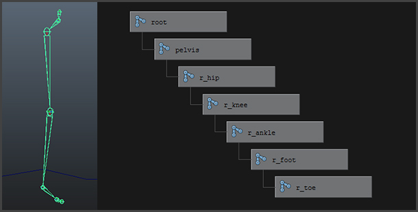
To align the leg joints more precisely to the center of the leg mesh, select the hip joint in the front orthographic view and move it along the X axis. All the joints below the hip in the chain will follow. To move a joint without affecting the position of the child joints, toggle the "Insert" key. Next, name the joints, "r_hip", "r_knee", "r_foot" and "r_toe". Naming the joints and associated objects will aid you tremendously when setting up additional rigging elements.
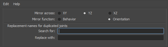
Once you have edited the joint placement for the right leg, you will want to mirror the joints for the left leg. Select the hip joint, and under the Skeleton menu, select Mirror Joint Options, and select "Orientation" as the mirror function. ("Behavior" is more appropriate for objects that move like wings in flight.) Rename the left leg joints, "l_hip", "l_knee", etc.
BIND THE MESH TO THE SKELETON

Once the skeleton is in position, you may bind the mesh to it. I like to bind the mesh to the skeleton at this stage, because it gives me the opportunity to test skeleton and make sure that it works properly with the mesh. I will be posting a separate tutorial about skin binding, but within this tutorial, I will offer a few basic guidelines.
Under the Skin pull down menu, select Bind Skin/Smooth Bind Options. When binding the mesh to the skeleton, you are in essence parenting the joints to the mesh on a per vertex basis. With Smooth binding, multiple joints can influence the position of one vertex. In this case, you will set the Maximum number of influences set to 3, which mean that as many as three joints may influence or "weight" any one vertex. Normalizing the Weights means that the cumulative influence of all joints on any vertex must equal 100% or "1". You will set this option to "Interactive" with a Dropoff rate set to 1.5.
Editing the proportional influence of joints on vertices is referred to as "skin weighting". Broad edits can be painted with the Paint Skin Weights Tool, which is accessible under the Skin pull down menu, under Edit Smooth Skin. Weighting can be further refined in the Component Editor under the Smooth Skins tab. The Component Editor is accessed through the General Editors, under the Window pull down menu.
The position the skeleton is in when it is bound to the mesh is called the "Bind Pose". I like to test the character at this point to make sure the mesh deforms properly as the joints are rotated. Further edits to the joint position and mesh can be made while the mesh is bound to the skeleton. If there are changes to the mesh, keep it as reference and duplicate it. If joints have been repositioned, duplicate the skeleton as well to from the new Bind Pose. Delete any history to the new mesh before rebinding. As long as the meshes are coincidental, the weighting values can be copied over from the old to the new (Skin> Edit Smooth Skin> Copy Skin Weights).
Once the mesh is weighted it should be saved in it own layer, which is referenced, so that it is visible, but not editable in the viewport. All the joints should be added to their own layer, as well. At this point the skeleton can be animated using Forward Kinematics and is ready for the application of Inverse Kinematic controls.
CREATE AN IK HANDLE
For your next step, you will create the IK Handle Tool for the right leg. There are two primary kinds of IK solvers in Maya: Rotate Plane IK solver (ikRPsolver) and Single Chain IK solver (ikSCsolver). The former is meant to be used in chains with multiple joints (like arms and legs, with either shoulder-elbow-wrist or hip-knee-ankle groupings) whereas the SCsolver is best for two-joint chains (like in a reverse foot rig). In chains with more than two joints the SCsolver can end up flipping the orientation of the bend after a certain extreme.
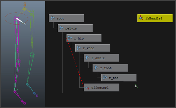
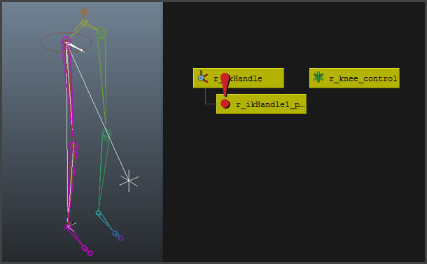
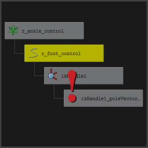
To create the IK handle, select the IK Handle Tool Options, under the Skeleton menu. Select the ikRPsolver and then click on the hip joint and then the ankle joint to create an IK handle. IK handles should be created from the inside of the joint chain towards the outside (so shoulder to wrist or hip to ankle, for example). You can see the rotation disc and the white pointer, which displays the orientation of the knee joint. Label it "r_knee_IK".
That’s almost good enough. However, if you play around with the handle you’ll find that certain extremes make the knee bend in crazy directions. To prevent this we can create a pole vector constraint.
ADD CONSTRAINTS AND CONTROLLERS TO THE IK
At its most basic level, an animation rig is created when one object is assigned to control another object's attributes. The most basic kind of rig is the parent-child relationship. Constraints allow you to specify more precisely the kind of control one object has over another. Constraints allow you to transform the values of an object's various attributes or channels by constraining those channels to the attributes or properties of another object. Channels include transformational values, like position, scale, and rotation, as well as color and visibility -- just about anything that can be animated. Also, whereas an object can have only one parent (but a parent can have multiple children), a constrained object may have multiple constraints.
When creating constraints, shift select the constraining object first and then the object which will be constrained. You will notice that this is just the opposite work flow when using the Parent command under the Edit menu. In that instance, the last object selected is the parent object.
The Pole Vector Controller
Before you can create the pole vector constraint, you must create a "controller" object which will act as the selection proxy for the pole vector. This will be the object the knee joints point towards. I usually use locators (Create> Locator) for pole vector controls. Label it "r_knee_control". Place the locator right in front of the knee joint. Hold down "v" snap the locator to the knee joint while in move mode and then move forward, constrained along the Z axis, until the locator is easily accessible in front of the mesh. Freeze transformations on the locator so that all of its transform values (rotate, translate, scale) are 0s and 1s (Modify > Freeze Transforms on selected objects). Freezing the transforms on control objects makes it easier for the animator to move objects to their default positions.
Select the "controller" object (the r_knee_control) and then the "constrained" object (r_knee_IK) and select Pole Vector Constraint from the Constrain menu. You will see a line now connecting the IK handle to the locator.
The Foot Controller
The foot controller will control the position and rotational orientation of the foot.
To create the foot controller, start by creating a NURBS circle and label it "r_foot_control". Place it at the base of the foot and roughly size it so that it encompasses the foot portion of the mesh. Shape the NURBS's CV's to roughly reflect a footprint. While in move mode ("w"), select the "Insert" key and snap the r_foot_control's pivot to the ankle joint by holding "v" as you move the pivot. Hit "Insert" again to end the pivot edit.
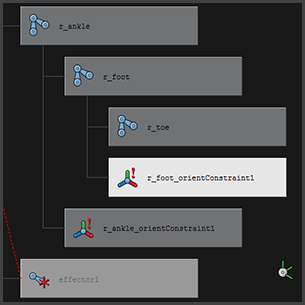
The r_foot_control will be used to orient the foot's rotation, so you will be applying an Orient constraint to the ankle joint. If you apply the constraint directly from the foot control to the ankle, the ankle joint will most likely twist out of place, so you will need to apply an intermediate object.
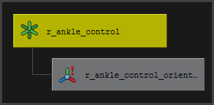
Create a null node (Create> Empty Node), name it "r_foot_orient" and snap its pivot to the right ankle joint and freeze its transforms. An empty node contains no geoemetry, but retains transformational information. A Select the right ankle joint and then the r_ankle_control and then select Constrain>Orient. The null node is now oriented to the ankle and its contraint can be removed by selecting it in the Hypergraph window and deleting it.
Next, parent the r_foot_control under r_foot_orient and then freeze the transforms. Select the r_foot_control, then the ankle joint and select Constrain>Orient. Since the foot control is placed under the r_foot_orient and its rotation is now only offset from its parent, it won't twist the ankle joint, when the ankle is constrained to it.
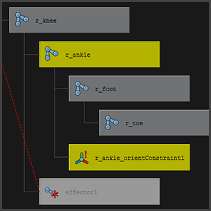
Parent the IK handle under the r_foot_control so that the r_foot_control can control the foot's position. Now you should be able to move the leg around freely and the knee will bend correctly and the foot's rotation will follow the foot_control's orientation.
The Toe Controller
More advance rigs use controls that automate the rotation of the toe joint as the foot rolls up. I will cover those in a separate tutorial. In this tutorial, you will create a simple rotational control for the toe joint, in a similar manner to the foot control. Create a NURBS circle and name it "r_toe_control". Rotate it 90 degrees so that it is perpendicular to the ground, and snap it to the foot joint and scale it so that is visible outside of the mesh.
The r_toe_control will be used to orient the toe's rotation, so you will be applying an Orient constraint to the toe joint. If you apply the constraint directly from the toe control to the toe joint, the toe joint will most likely twist out of place, so you will need to apply an intermediate step, as you did with the ankle and foot controls. Create a null node and call it "r_toe_orient", snap it to the foot joint and freeze the transforms. Select the foot joint and then the r_toe_orient and Constrain>Orient. Remove the constraint from the r_toe_orient. Parent the r_toe_control under the r_toe_orient in the Hypergraph window. Freeze the r_toe_control transforms. Now select the r_toe_control and then the foot joint and select Constrain> Orient. Parent the r_toe_orient under the r_foot_control.
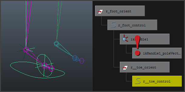
Now select the r_toe_control and then the foot joint and select Constrain> Orient. Parent the r_toe_orient under the r_foot_control.
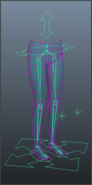
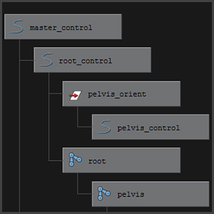
The Master Controller
Create a master control object that can control the transform values for the entire rig. Create a NURBS circle at the base of the model, edit its CV's to indicate directional changes as seen in the image. Snap its pivot to the root joint and name it "master control". Scale the controller so that it is easily selected and visible outside of the mesh. Freeze its transforms.
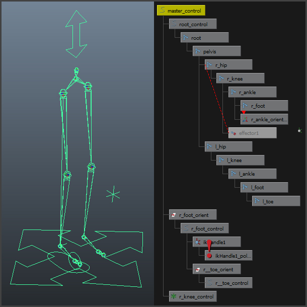
The Root Controller
This controller controls the vertical motion of the pelvis as a it is raised and lowered in a walk cycle. Create a NURBS circle and edits its shape to match the sample in the image. Snap its pivot to the root joint and name it "root control". Freeze its transforms. Parent the root joint under the root control. Parent the r_knee_control and r_ankle_control under the master controller so that they move together with the entire rig.
Constrain The Pole Vector To Move With The Leg
As you have seen, its pretty easy to set up a basic pole vector controller. As you test your rig, you will see that as you move the foot controller the knee controller remains in place requiring you to counter-animate. If you want to make sure the knee controller follows the knee, you will need to set an extra constraint.
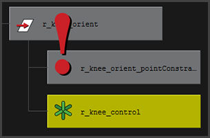
Create a null object (an empty group node) and call it "r_knee_orient" and snap it to the knee joint. Freeze its transforms and point-constrain it to the right knee joint The point constraint directly controls translation by constraining the position of an object to one or more targets.. Select the knee controller (the locator object) and place it under the r_knee_orient. By grouping the knee controller under a null node (an empty group node), we can apply constraints to the null node, but still maintain the offset values to the knee controller. Make sure the knee controller's transforms are still set to "0" and "1" and if not, just freeze the transforms again.
As you move the foot controller, the pole vector will follow.
Now apply the same controls and constraints to the left leg.
The Pelvis Rotate Controller
As you walk, there is a natural shift of weight from one hip to another to create a swaying effect. To finish the rig, you will add a control to the hips to create that sway. Create a NURBS circle and snap move its pivot to align with the pelvis joint. Freeze the transforms on the circle and name it "pelvis_control". Edit the CV's to create 4 points that are assessable beyond the mesh.
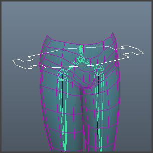
Create a null node and label it pelvis_orient. Snap the pivot for the pelvic_orient to the pelvis joint. Shift select the pelvis_joint and then the pelvis orient and select Constrain > Orient. Delete the constraint. Parent the pelvis control under the pelvis orient and freeze the pelvis control' transforms. Select the pelvis control and then the pelvis joint and select Constrain > Orient. Parent the pelvis orient undert the root control.
GO ANIMATE!
You are now ready to apply a walk animation to bipedal character, which I will cover in my next tutorial. Add the IK handles to the joint layer and hide it. Add your control objects to a separate layer. Make sure your mesh is visible, but be sure to place it in a referenced layer to avoid selecting it by mistake in the viewport when you animate. Add a floor object and have fun animating!
![]()
![]() (Hover curser over image to start play)
(Hover curser over image to start play)
BTW, to test render "joints", use the Hardware Render Buffer feature (Window > rendering editors > hardware render buffer). Once selected, select Render > Attributes and change the background color to grey or white ... and then select "Transform Icons". You can add some anti-aliasing with "Line Smoothing" under "Render Modes".
![]()